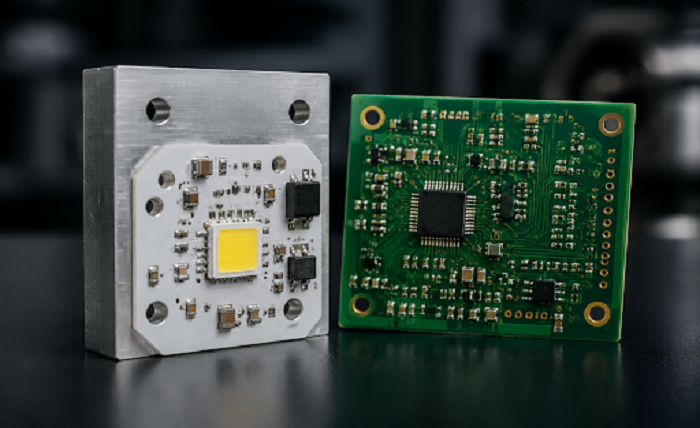
Standard FR4 has been the workhorse substrate for decades, but it has a fundamental limitation: it’s a terrible thermal conductor. The epoxy-glass construction that makes FR4 cheap and versatile also traps heat. For designs that dissipate more than a few watts per square inch, that trapped heat shortens component life, shifts electrical parameters, and eventually causes field failures.
Aluminum PCBs (also called Metal Core PCBs or MCPCBs) solve this by replacing the epoxy core with an aluminum base plate separated from the copper circuit layer by a thin thermally conductive dielectric. The result is dramatically better heat transfer—but it comes with design trade-offs and a higher price tag.
What Sets Aluminum PCBs Apart from FR4
The fundamental difference between these two materials comes down to one word: construction.
An FR4 PCB uses woven fiberglass cloth impregnated with epoxy resin as its core material. Copper foil is laminated to one or both sides, and the multi-layer stackup is bonded with prepreg sheets. FR4’s thermal conductivity sits at roughly 0.3 W/mK—close to that of wood or plastic.
An Aluminum PCB replaces the fiberglass core with an aluminum alloy plate (typically 5052 or 6061). Between the copper circuit layer and the aluminum base sits a thin dielectric layer that provides electrical insulation while conducting heat. The aluminum core itself has a thermal conductivity of 130–170 W/mK, though the effective system conductivity is limited by the dielectric layer, typically ranging from 1.0 to 3.0 W/mK for standard materials and up to 6–8 W/mK for high-performance dielectrics.
Structure Comparison
| FR4 PCB | Aluminum PCB (MCPCB) | |
|---|---|---|
| Core Material | Woven glass + epoxy resin | Aluminum alloy (5052/6061) |
| Dielectric Layer | FR4 prepreg (electrical grade) | Thermally conductive dielectric |
| Copper Layers | 1–64 layers | Typically 1–2 layers |
| Thermal Conductivity | ~0.3 W/mK | 1.0–8.0 W/mK (system) |
| Typical Thickness | 0.2 mm–12 mm | 0.8 mm–3.2 mm |
| Weight | Light | Heavier (metal core) |
| Relative Cost | Baseline | 2×–5× FR4 |
Thermal Performance: The Deciding Factor
The most important specification when comparing Aluminum PCB vs FR4 isn’t listed on most datasheets. It’s the thermal resistance from the component junction to the ambient environment, and it determines whether your design runs at 85°C or 125°C at the same power level.
Why FR4 Struggles with Heat
FR4’s thermal conductivity of 0.3 W/mK means that for every millimeter of board thickness, heat experiences significant resistance. Designers typically mitigate this with thermal vias—arrays of plated holes that conduct heat from the top copper layer to an internal ground plane or bottom copper pour.
The problem is that thermal vias still rely on thin copper plating (typically 1 oz or 35 µm) running through an FR4 barrel. The effective thermal conductivity of a via field might reach 5–10 W/mK in localized areas, but the overall board performance remains poor.
How Aluminum PCBs Dissipate Heat
An aluminum PCB’s heat path is much shorter and more direct: from the component through the copper pad, through the thin dielectric (typically 50–200 µm), and into the aluminum core. The core then acts as an integrated heat spreader, distributing the heat across the entire board area.
Here’s the math for a simple comparison. For a power component dissipating 5W on a 25 mm × 25 mm area:
| Parameter | FR4 (with vias) | Aluminum PCB |
|---|---|---|
| Board Thickness | 1.6 mm | 1.6 mm |
| Dielectric Thickness | 1.6 mm (entire substrate) | 0.1 mm (thermal dielectric) |
| Effective Thermal Conductivity | ~0.3 W/mK | ~2.0 W/mK |
| Thermal Resistance (Rth) | ~8.5°C/W | ~0.8°C/W |
| Temp Rise at 5W | ~42.5°C | ~4.0°C |
In practical terms, the same component running at the same power will run 30–50°C cooler on an aluminum PCB compared to FR4 with standard via management. That difference directly translates to longer component life, higher reliability, and the ability to drive more power through the same footprint.
When Aluminum PCBs Are Worth the Cost
The 2×–5× price premium for aluminum PCBs isn’t justified for every design. Here’s where the investment pays for itself—and then some.
High-Power LED Lighting
LEDs are heat-sensitive devices. Junction temperature above 85°C accelerates lumen depreciation dramatically. A typical 50W streetlight LED array dissipating 50W across a 100 mm × 100 mm board would hit junction temperatures of 110°C+ on standard FR4, even with thermal vias. On an aluminum PCB, the same array stays at 75–80°C.
For a deeper understanding of thermal management strategies and material selection, please refer to this article: Aluminum PCB: Complete Guide to Metal Core Circuit Boards
Power Electronics and Voltage Regulators
DC-DC converters, voltage regulator modules, and motor drivers all generate concentrated heat that FR4 struggles to spread. A 10A buck converter with a 90% efficiency rating dissipates 1W in switching losses alone—enough to create a localized hot spot on FR4 that shifts component parameters. Aluminum PCBs spread that heat across the entire board surface, often eliminating the need for a dedicated heatsink.
Automotive Electronics
Automotive environments push PCBs to their limits: under-hood temperatures of 85°C–125°C combined with engine vibration and thermal cycling from cold starts. Aluminum core PCBs provide the mechanical rigidity and thermal performance needed for LED headlight modules, battery management systems, and motor controllers.
RF Power Amplifiers
High-power RF amplifiers generate significant heat and require stable dielectric properties. While standard FR4’s dissipation factor degrades noticeably above 1 GHz, aluminum PCB constructions using high-frequency dielectrics can handle both the thermal load and the electrical requirements.
Applications Summary
| Application | Why Aluminum PCB Wins | Typical Temp Reduction |
|---|---|---|
| High-power LED arrays | Direct thermal path prevents lumen depreciation | 30–50°C lower junction temp |
| DC-DC converters / VRMs | Spreads heat without bulky heatsinks | 20–40°C lower board temp |
| Automotive LED headlights | Handles 85–125°C ambient + vibration | Prevents thermal runaway |
| RF power amplifiers | Low-loss dielectric + metal core cooling | 15–30°C lower device temp |
| Motor drives | Sustains high-current with thermal stability | Extends MOSFET lifetime 3× |
| Solar micro-inverters | Outdoor reliability + thermal cycling resistance | 25–40°C cooler hotspot |
When FR4 Is Still the Better Choice
Aluminum PCBs aren’t a universal upgrade. In many designs, FR4 remains the right material.
Multilayer Designs (4+ Layers)
Aluminum PCBs are fundamentally limited to 1–2 copper layers because the metal core prevents standard plated through-hole connections. If your design needs 4, 6, or 8 layers for signal routing, FR4 is the only practical choice unless you’re willing to use a hybrid construction that combines an aluminum base with multilayer FR4 lamination—a significantly more expensive option.
Cost-Sensitive Consumer Products
For high-volume products operating below 2–3W of dissipation, the added cost of an aluminum PCB simply doesn’t make sense. A $0.50 heatsink on a standard FR4 board often solves the same thermal problem as a $2.00–$5.00 aluminum PCB premium.
Designs Requiring PTH Components
Standard through-hole components are difficult to implement on single-layer aluminum PCBs because the metal core creates an electrical short if a plated hole contacts the substrate. While PTH can be done on hybrid or 2-layer MCPCB constructions, it adds manufacturing complexity and cost.
High-Frequency Designs (Pure FR4)
For RF designs above 1 GHz using standard FR4, the dissipation factor (0.02–0.025) already causes significant signal loss. Adding an aluminum core doesn’t fix the electrical problem—you’d need to move to RF-grade laminates (Rogers, Isola, etc.) regardless of thermal considerations.
When to Stick with FR4
| Scenario | Why FR4 Wins |
|---|---|
| 4+ layer designs | Aluminum limited to 1–2 layers |
| Power < 2W total | Cost premium not justified |
| High-volume consumer products | $0.50 heatsink cheaper than MCPCB |
| Through-hole components required | PTH on aluminum is complex and costly |
| RF above 1 GHz | Need Rogers/PTFE regardless of core |
Cost Comparison: Aluminum PCB vs FR4
Pricing varies by volume, layer count, and specifications, but the general relationship is consistent.
| Board Type | Prototype (10 pcs) | Low Volume (500 pcs) | Mid Volume (5,000 pcs) | Notes |
|---|---|---|---|---|
| 2-Layer FR4, 1.6mm | $5–15/board | $1.50–3.00/board | $0.80–1.50/board | Baseline cost |
| 4-Layer FR4, 1.6mm | $15–40/board | $4–8/board | $2–4/board | Standard for complex designs |
| 1-Layer Al PCB, 1.6mm | $12–30/board | $3–6/board | $1.50–3.00/board | 2× FR4 for 1-layer |
| 2-Layer Al PCB, 1.6mm | $25–60/board | $6–12/board | $3–6/board | ~3× FR4 2-layer |
| 2-Layer Al PCB + Hi-Perf Dielectric | $40–80/board | $10–20/board | $5–10/board | 5× FR4, best thermal |
Several factors push aluminum PCB costs higher than FR4:
- Raw material cost: Aluminum substrates cost 2–3× more per square foot than standard FR4
- Dielectric material: High-performance thermally conductive dielectrics add significant cost
- Processing complexity: Aluminum requires specialized routing tools (diamond-coated), different drilling parameters, and separate lamination processes
- Layer limitations: You can’t stack layers on aluminum like FR4, so complex routing may force larger board sizes
- Surface finish compatibility: Some finishes require process adjustments for aluminum substrates
The key insight: total system cost matters more than board cost. If an aluminum PCB eliminates a $2 heatsink, a $5 fan, and reduces assembly labor, the 2× premium at the board level becomes a net savings.
Design Considerations for Both Materials
Switching between FR4 and aluminum isn’t a drop-in replacement. The design rules differ significantly.
Trace Width and Current Capacity
Aluminum PCBs handle higher currents per trace width because the metal core helps pull heat away from the trace. A 1 oz copper trace on an aluminum PCB can carry approximately 15–25% more current than the same trace on FR4 before reaching the same temperature rise.
| Trace Width | 1 oz Cu, FR4 (10°C rise) | 1 oz Cu, Al PCB (10°C rise) | 2 oz Cu, Al PCB (10°C rise) |
|---|---|---|---|
| 10 mil (0.25 mm) | 0.8A | 1.0A | 1.5A |
| 20 mil (0.5 mm) | 1.5A | 1.9A | 2.8A |
| 50 mil (1.27 mm) | 3.0A | 3.7A | 5.5A |
| 100 mil (2.54 mm) | 5.0A | 6.2A | 9.0A |
Thermal Via Management
On FR4 boards, thermal vias are essential. On aluminum PCBs, they’re largely unnecessary—the entire metal core acts as a heat spreader. This simplifies the stackup and eliminates the cost of via fabrication.
Surface Finish Selection
Most standard surface finishes are compatible with aluminum PCBs, but there are important caveats:
| Surface Finish | Compatibility | Notes |
|---|---|---|
| HASL (Lead-Free) | Good | Standard option, works well |
| ENIG | Excellent | Best for fine-pitch and thermal pads |
| OSP | Limited | Not recommended for high-temp applications |
| Immersion Silver | Good | Compatible, good solderability |
| Hard Gold | Excellent | For high-wear or edge connector applications |
Aluminum PCB vs FR4: The Bottom Line
Choose FR4 when your design has low thermal demands (under 0.5W/in²), requires 4+ layers, or is extremely cost-sensitive. FR4 remains the default for good reason—it’s proven, flexible, and inexpensive.
Choose Aluminum PCB when thermal performance is critical. If your design runs hot, uses high-power LEDs, operates in automotive or outdoor environments, or needs to eliminate bulky heatsinks, the cost premium for aluminum pays for itself through improved reliability and reduced system complexity.
A reliable manufacturing partner who understands both materials can make this decision easier. A company like PCBAndAssembly, for instance, processes both FR4 and aluminum substrates daily and can provide real-world guidance on material selection, dielectric options, and design trade-offs during the DFM review—helping you avoid costly mistakes before production starts.
FAQ
How much more does an aluminum PCB cost compared to FR4?
A standard 1-layer aluminum PCB costs approximately 2× to 3× more than an equivalent 2-layer FR4 board at prototype quantities. The premium narrows to 1.5×–2× at production volumes. High-performance dielectrics can push the multiplier to 4×–5×. However, the total system cost often favors aluminum when heatsinks, fans, and reliability costs are factored in.
Can aluminum PCBs support surface mount components only?
Yes. Most aluminum PCBs are designed for SMT components because the metal core prevents standard plated through-hole connections. Through-hole components require hybrid constructions or clearance holes drilled through the aluminum, which adds cost. Always plan for SMT assembly when designing for aluminum substrates.
Is an aluminum PCB the same as a metal core PCB (MCPCB)?
Aluminum PCBs are the most common type of metal core PCB, but MCPCBs can also use copper or steel cores. Copper offers higher thermal conductivity (~398 W/mK) at a significantly higher cost and weight. Steel cores are cheaper but offer lower thermal performance. Aluminum provides the best balance of cost, weight, and thermal performance for most applications.
What thermal conductivity should I look for in an aluminum PCB?
For standard LED and power applications, a dielectric with 1.5–3.0 W/mK is sufficient. For high-power designs (MOSFETs, IGBTs, laser diodes), specify 4.0 W/mK or higher. Below 1.0 W/mK, the thermal benefit over FR4 is marginal and may not justify the cost premium.
Can aluminum PCBs handle high voltages?
The aluminum substrate itself is electrically conductive, so the dielectric layer provides the only insulation between your circuit and the metal base. Standard dielectrics offer breakdown voltages of 2–6 kV depending on thickness. For designs above 250V or in high-humidity environments, specify a thicker dielectric (100–200 µm) and confirm the breakdown voltage rating with your manufacturer.
How many copper layers can an aluminum PCB have?
Standard aluminum PCBs are limited to 1–2 copper layers. Two-layer constructions use pre-patterned copper on both sides of the dielectric, with the aluminum core acting as the thermal spreader. Hybrid constructions that bond multilayer FR4 sections to an aluminum base are possible but significantly more expensive—typically used only when both high layer count and thermal management are non-negotiable.
What is the maximum operating temperature for aluminum PCBs?
The aluminum core itself handles temperatures well above 300°C, but the limiting factor is the dielectric material. Standard thermal dielectrics are rated for 130–150°C continuous operation. High-temperature dielectrics can handle 200°C+. For designs exceeding 200°C, consider alternative thermal management strategies or ceramic substrates.
Do aluminum PCBs require special soldering profiles?
Aluminum PCBs require slightly different reflow profiles than standard FR4 because the metal core acts as a heat sink, drawing heat away from the solder joints during reflow. Your assembly partner should increase preheat time by 10–15% and verify that the peak temperature is reached at the solder joint, not just on the board surface. A manufacturer experienced with metal core substrates will adjust the profile automatically.
Conclusion
The Aluminum PCB vs FR4 decision ultimately comes down to one question: does your design produce enough heat to justify the material premium? For low-power, cost-sensitive, or multilayer designs, FR4 remains the practical choice. For any application where thermal management drives reliability—LED lighting, power electronics, automotive systems, or high-current designs—the investment in aluminum PCBs pays for itself in longer product life, simpler thermal design, and fewer field failures.
If you need to bring your PCB design to life, PCBAndAssembly should be at the top of your list. Start your project today with PCBAndAssembly to experience the speed, quality, and expertise that will help you succeed.